Smart Home with Multiple Boards and Programming
Overview
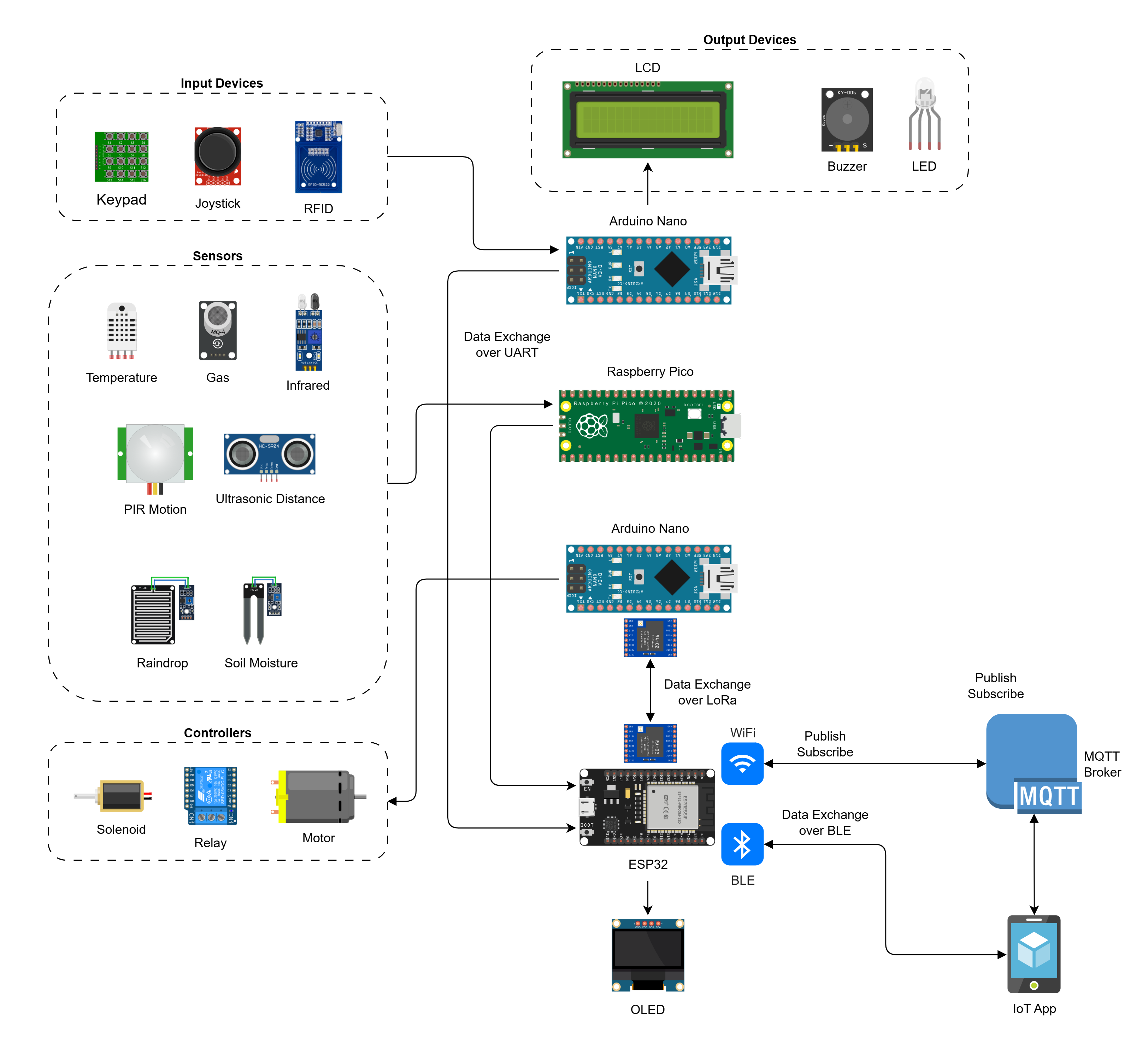
The second Smart Home IoT solution you will learn to assemble and program, will build on the two circuits from the first solution and add another two circuits.
One of the two new circuits will be a Nano connected to input and output devices. The second new circuit will use the ESP32 baord which can be used for WiFi and BLE communication.
With ESP32 handling the WiFi connection and the publish/subscribe of data with the MQTT broker on the cloud, we will not need Node-RED in this solution.
Instead of sending data to and receving control signals from Node-RED, one Nano and the Pico circuits will exchange data with the ESP32 circuit via UART. And the second Nano will exchange data with the ESP32 circuit over LoRa.
In this project we will also introduce our IoT App which will connect to the ESP32 circuit via BLE and exchange data and control signals with the IoT App.
Architecture
Solution Components
In this part of the learning path you will learn to design, assemble, and program four circuits that will make up the Internet of Things solution.
All circuits are connected to a shared breadboard mounted power supply and also connected by a common ground to each other. Three of the four circuits share a common LCD. The power and the LCD connections are shown separately across all boards. You may choose to make the common connections first or the individual board connections first, as you prefer.
This solution will have the following components:
Circuit Diagram
The circuit diagram for the complete solution with all circuits connected is shown below:
